I’m currently working on a project to create a reasonably accurate drawing of the Quapaw… perhaps to be printed as a poster (if it comes out decent).
In trying to find references for this project, I stumbled on the “Dimensions and Data” page from a BUSHIPS “General Booklet of Plans” for an ATF*. In it, it’s noted that the draft above keel (amidships) was designed at 13′ 9-1/2″. This would be the waterline. Looking at this photo of ATs being built (by the way, where was the Quapaw?!?!):
http://www.navsource.org/archives/09/39/093910709.jpg
…in that photo, you can see that the waterlines seem to be in agreement with that 13′ 9″ number (between the 3 and 4 on the stem markings). However, in pretty much everything else I’ve ever seen in photos or documentation (and personal experience), draft/waterline for AT(F)s is shown as 15′ 4″, (the waterline is painted above the 5 on the stem). The difference basically moves the painted waterline from just below the exhausts (on the “side-burner” AT(F)s), to just above them.
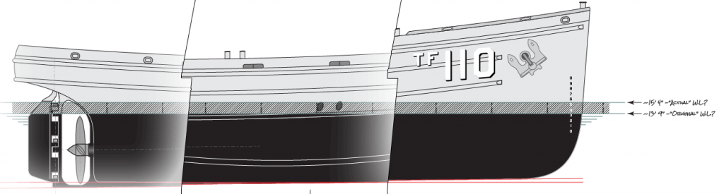
For my drawing, I’m going to use the 15′ 4″ figure, since that’s where I painted it on the Quapaw when I was aboard… but I’m curious as to why the draft/waterline on these ships seems to have moved .
Does anyone have any thoughts or ideas on this?
* I understand that these drawings were NOT meant to be 100% accurate – like actual ship’s plans would be.
The post The Case of the Wandering Waterline? appeared first on USS Quapaw ATF-110.